CUT TO LENGTH LINE - ZTRFM
Zhongtuo cut to length line
Thin sheet simple cut to length with slitting machine
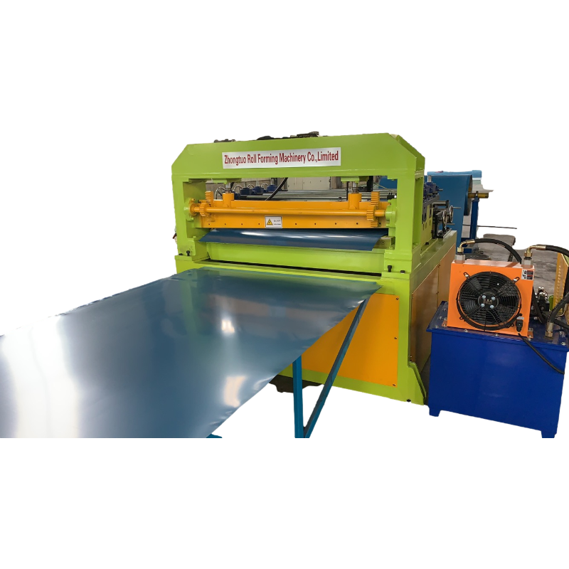
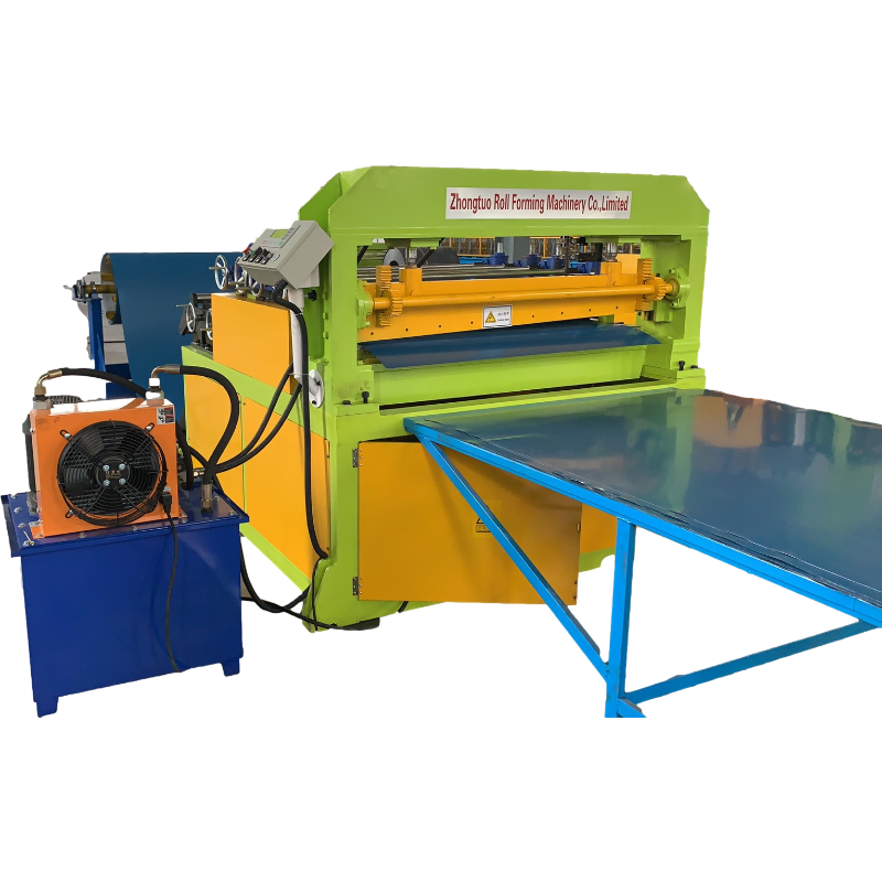
ZT automatic cut to length line
Brief introduction
ZT automatic cut to length line are mainly used to the uncoiling , leveling and shearing of the steel coils and prepare for the next process.
I. Technical Parameter:
1. Specifications:
a. applied to : HR,CR
b. Tensile strength:δb≤500Mpa,δS≤300Mpa
c. thickness:0.5-2.0mm
d. width:500-1500(Max)
e. coil ID: φ508mm
f. coil OD:φ1600mm(Max)
g. weight :15T(Max)
h. diameter of leveling rollers: φ65mm
i. distance of leveling rollers:70mm,
j. material of leveling roller:GCr15,hardness:HRC55-60
k. total weight of machines:around 30T
2. Finished products parameters:
a. diagonal tolerance:≤±1mm/2000mm
b. length tolerance:≤±0.5mm/2000mm
3. Other parameters :
a. power :380V/50Hz/3Ph
b. line speed:0-60m/min
c. capacity :around 100Kw
d. area of the whole production line(about) 25m(L)X7m(W)
e. people of operation: 1 technician and 2 general workers
f. color of the machines: grass green
Ⅱ. Working Flow
1. Hydraulic entry coil car
*The car can move levelly and vertically, which is convenient for putting the steel coils into the de-coiler.
*It is driven vertically by hydraulic cylinder with four guide pillars.
*The level movement is driven by cycloid motor.
*The capacity it can carry is 15 Tons(Max).
2. Hydraulic cantilever de-coiler
* Supporting the coils and doing uncoiling. The capacity is 15Tons(max).
*It adopts the hydraulic oil cylinder to make the decoiler expandable and fit to the inner diameter of coils. It is equipped with the cantilever.
*100N.m moment motor drive the coils running and can do forward and reverse running as well as do the decoiling with tension.
*The core can ensure the expand range φ508 of the coils inner diameter.
*Structure: welding by the steel plates and profiled bar.
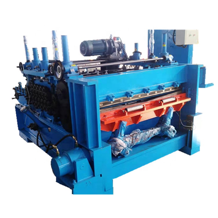
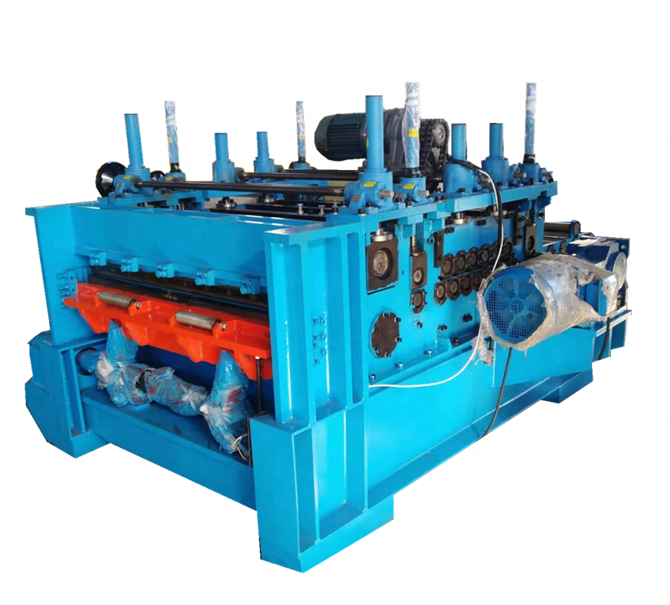
3. 6-h pre-leveling machine
*It can straighten the rough plate and guide strip right after entering the process
*Mechanical structure: it is composed of two rows leveling roller, two rows middle supporting roller, 2 groups of supporting rollers, driving device, 2 pinch rollers and frame. Each roller both of ends drive with roller pin bearing, 17 leveling rollers all the main driving rollers, the diameter is 65, roller distance is 70; 19 intermediate roll, the diameter is 65; 2 pinch rollers coated with polyurethane on surface, it can prevent the sheet. Two groups of supporting rollers, on each group, each of the three rows.
*The function of the Intermediate roller is to balance the leveling rollers force and reduce the friction to the rollers and reduce the friction plate, ensure high quality surface leveling effect
*The function of the supporting roller is to support leveling roller. It can adjust separately to adapt to the different type
*The working rollers can be adjusted the gap electrically which is controlled by 2 hand wheels to ensure the leveling quality.
*Driving model: all the independent rollers and gear box are driven by 55kw frequency control motor
*Roll process: raw material- rough machining – hardened HRC55-60 -finishing grinding- hard chromium plating
* Automatic lubrication system
4. Loop
*It uses the 2 groups of eyes to control the speed buffer between decoiler and slitting *achines.
*T eye is controlled by PLC.
*Function: it is used to eliminate the different speed and make the plates which in wrong rail to back the right way. At first, it is used the oil cylinder to lifting the supporting and transition plates to make the head pass. When working, the transition and supporting plates lift down, the steel plates will be stored in the pit.
5. Side guide device
*It uses the vertical roller-wheel on the both sides to direct strips into straightening device and cutting machine.
*The stand rollers on both sides are adjusted by leadscrew. The range of the width is 500-1500mm.
6. Servo precision straightening machine
*It is controlled by servo electromotor and used to regulate for high speed feed and precise length control.
*The operation is done at the control table with programmable control.
*Drive model: 15 KW servo motor with precise decelerating transmission and synchronous to transport the belt to feed rollers
7. High speed Cutter
*Shear model: cut from up to down hydraulically which is cooperate with the signal direct from the feeder and shear automatically
*Adopt gap adjusting designs to cut the materials and can shear 2mm steel plate safely after heat treatment
8. Transportation table
*Transportation belt is skid proof and wearable
*Drive: cooperate with the line speed and is transmitted by 4KW frequency control motor
9. Hydraulic lifting table
*The length of plates can range from 500-6000mm( which can be customized)
*The width cab be ranged from 500 to 1600mm.
10. Pneumatic stacker device
*The plates are piled pneumatically and PLC controls the lifting.
*Three 0.75kw motors drag to adjust the width and the length.
*It is equipped with the wind device which cooperates with the high pressure fan to prevent the sheets from friction.
11 . Exit coil car
*Set horizontal discharge car, neat code sheet output production lines, to ensure the continuity of production of sheet metal.
*Set the cycloid gear motor output power.
12. Pneumatic system
* The pneumatic system is composed of the air power(prepared by the buyer), air source treatment components , salennoid, relevant pipeline and air cylinder, etc. The components such as salennoids are adopted high quality products.
* Technical parameters: stress of air source: 0.4-0.6Mpa. The capacity:1m³ /min.
13 Hydraulic system
* Ensure the using of every hydraulic part.
*The working pressure of the hydraulic system is 6.3-16Mpa.
14. Electrical system
*Adopt the frequency conversion motor controls mode and PLC control mode, It is controlled by LCD screen with fixed-length cutting by codes and count automatically.
Ⅲ. The foundation engineering of the equipment
*The seller will provide the buyer the foundation plan of the equipment in 60 days after signing contract.
*The construction and monitoring of all the foundation engineering of the equipment are in the control of the buyer.
*The foundation holes are reserved holes, to match the foot holes of equipment.
*After the equipment has been installed, the buyer is responsible for the foundation hole irrigation mud.


